

Building Water Supply Monitoring via Computer and Mobile Browsers and an On-Site Serial Display
The water supply system is already managed by a PLC, with data available for inlet flow, outlet flow, and water level. But if that information stays inside the control cabinet, property maintenance staff still have to visit the site to check the current supply conditions. Can they view the same system from a computer or phone browser while in the office or on inspection rounds, and operate the inlet and outlet switches when conditions allow?
Consider a typical building water supply scenario: the PLC monitors inlet flow, outlet flow, and water level, and controls the inlet and outlet switches. With a Woody industrial intelligent gateway connected, a local water supply App can be developed around these existing variables. Staff can use a phone browser to access its mobile-friendly page remotely through the gateway management platform, without developing a separate installable mobile client for this approach. The same application supports status viewing and authorized operation from a computer browser, while a serial display beside the control cabinet shows system status.
The PLC Controls Water Supply; the Gateway Connects the Viewing Interfaces
This solution does not move water supply control logic to a web page. Instead, it keeps responsibilities clearly separated:
| Component | Role in the solution |
|---|---|
| PLC | Acquires field signals, executes inlet and outlet control and on-site interlocks, and makes the required variables available to the gateway |
| Woody gateway | Reads PLC data, organizes variables, and hosts a custom local application; receives validated operation requests and writes permitted control variables to the PLC |
| Local water supply App page | Runs on the gateway, displays flow, water level, switch status, and communication status, and provides an operating interface for authorized staff |
| Gateway management platform | Provides an authorized remote entry point to gateway internal pages; the gateway still hosts the local App page, business logic, and data processing |
| Phone browser | Opens the mobile-friendly local water supply App page through the gateway management platform and submits requests according to operation permissions; no separate installable mobile client is required |
| On-site serial display | Receives data organized by the gateway using a protocol supported by the display, and shows water supply status; display-based control functions are outside the scope of this article |
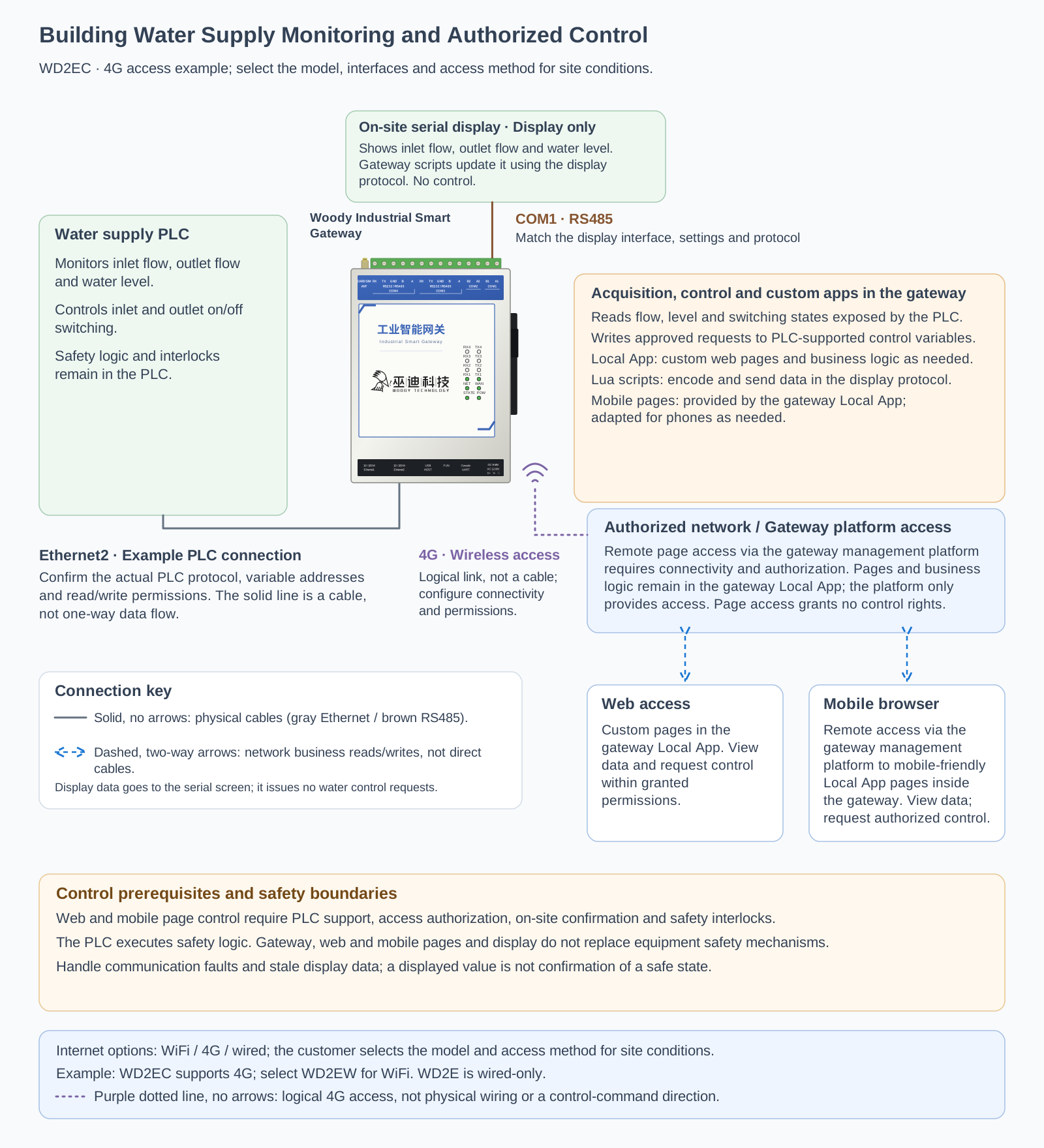
The diagram uses a PLC supporting Ethernet communication and an RS485 serial display as connection examples. The WD2E is shown as an illustration of the device's appearance. The actual gateway model, PLC protocol, and the serial display's electrical interface and communication protocol must be confirmed for the site. If an existing serial display is connected directly to the PLC, retain and check that topology rather than simply reconnecting it or adding a parallel connection to the communication lines.
Understand Water Supply Status in Computer and Phone Browsers
When maintenance staff open the water supply page, they first see inlet flow, outlet flow, and water level, then check the inlet and outlet switch status. A water supply schematic can organize this information, making it easier to understand where water enters, where it leaves, and the current water level than a list of variable addresses would.
The gateway's local App framework supports backend logic written in Lua and frontend pages written in JS/CSS/HTML. It also supports binding variables through graphical configuration approaches such as SVG. The water supply page can run locally on the gateway, without deploying an additional application server just for local display. The actual screens, variable mappings, and operation logic still require configuration or development; connecting the gateway does not provide a complete, ready-made water supply management application.
For mobile access in this solution, staff open the gateway management platform in a phone browser and, with the required access authorization, remotely access the mobile-friendly local water supply App page embedded in the gateway's Web management interface. A "gateway-local App" is a business application running on the gateway, not a native phone App. The page still needs configuration or development and mobile adaptation, but this approach does not require a separate downloadable, installable mobile client. The platform provides the remote entry point; the gateway continues to provide the page, business logic, and data processing. Integrating a separate App through REST API is only an optional extension, not a prerequisite for this solution. Access to gateway internal pages does not imply access to downstream devices' web pages or automatically grant configuration or device control permissions.
All three display interfaces should use consistent variable meanings and units, and indicate when data was last updated, the communication status, and whether the data is valid. If communication with the PLC is lost or data becomes stale, they should show "Communication fault" or "Data out of date" rather than continue presenting old water levels and flow readings as current values. Switch status should preferably use actual feedback from the PLC. If only command values are available, they must be clearly labeled "Command status" and must not be treated as proof that a switch has completed its action.
Operating Inlet and Outlet Switches Requires Execution Feedback
When inlet or outlet operation needs to be adjusted according to site procedures, authorized staff can initiate a switch operation from the local water supply App page in a computer or phone browser. This requires the PLC to support the relevant writes, the operator to have access authorization and operation permissions, on-site confirmation to be completed, and on-site safety interlocks to permit execution. Being able to open the page does not grant control permission, and the page may not bypass the PLC's safety mechanisms.
Each operation should follow a clear closed-loop process:
- The page displays current water level, flow, switch feedback, and communication status so that the operator can confirm the target and on-site conditions.
- The application validates identity, operation permissions, data validity, and the conditions that permit operation, then requires confirmation of the specific action.
- The gateway writes the request to the agreed PLC control variable. The PLC decides whether to execute it according to its own logic.
- The page reads the PLC's execution result or status feedback and distinguishes between "Request sent," "Execution confirmed," and "Unconfirmed / failed."
A successful write does not mean that an on-site switch has actually opened or closed. If communication times out or feedback is missing, the application must not simply display "Operation complete," nor should it automatically resend control requests unconditionally. The priorities of remote and on-site operation, whether manual intervention is allowed in automatic mode, and how expired requests are handled must all be agreed during integration alongside the PLC control logic.
The local water supply App page viewed in computer and phone browsers is a routine maintenance interface. It does not perform emergency stops, overflow protection, or other safety control functions. Even if the web page is closed, the phone goes offline, or gateway communication is interrupted, the PLC and on-site safety devices must continue to handle local control and protection independently.
A Serial Display Beside the Control Cabinet Can Show the Same Status
Staff performing on-site inspections do not always need to open their phones. A serial display can bring inlet flow, outlet flow, water level, and switch feedback together, making it convenient to check current conditions beside the control cabinet.
In this example, the gateway first reads PLC variables, then uses Lua scripts to organize display fields, units, and status text, and sends them over a serial connection using a protocol supported by the display. The display handles presentation; the gateway handles data processing and communication adaptation. The specific connection requirements must be confirmed before implementation.
The display should also have a strategy for indicating communication faults or invalid data. For example, the adaptation logic can configure an update-timeout indicator so that the display does not keep showing old values without a warning after the gateway stops updating them.
What to Confirm Before Integration
- PLC communication and data points: Model, available protocols, variable addresses, data types, flow and water level units, and the command and feedback points for the inlet and outlet switches.
- Control boundaries: Writable variables, on-site confirmation procedures, access permissions, automatic/manual modes, priorities of on-site and remote operation, safety interlocks, and exception handling.
- Serial display adaptation: Model, RS232 or RS485 electrical interface and wiring, communication parameters, write messages, address or field mappings, display pages, and update interval; check the connection arrangement of any existing display first.
- Web and mobile interfaces: Configuration or development of the gateway-local water supply App page, mobile layout and browser compatibility, authentication, and separate checks for page access and operation permissions; a separate mobile client or REST API integration is not required for browser access.
- Off-site access: Set up gateway management platform integration, access authorization, and the required network connectivity so that staff can reach the gateway's internal page through the platform. The platform is a remote entry point, not the host of the water supply business logic. Do not expose PLC control interfaces directly to the public Internet or infer access to downstream devices' web pages or control permissions from page accessibility.
From Checking at the Cabinet to Viewing as Needed and Operating with Authorization
The value of this solution lies in turning water supply information already held by the PLC into interfaces that staff can use in everyday maintenance. The office computer browser, the inspector's phone browser accessing the gateway-local page through the gateway management platform, and the serial display beside the control cabinet serve different purposes, but the data they show has consistent meanings, and operations have clearly defined permissions and feedback. Mobile access uses the gateway's local business application, without requiring a separate installable phone App.
For a building water supply system already controlled by a PLC, start by displaying flow, water level, and switch status. Then enable the necessary operation interfaces once device support and safety conditions have been confirmed. The Woody gateway connects data to interfaces, making everyday checks more convenient and providing feedback to verify each authorized operation.