

FANUC CNC Data Collection, Production Counting, and OEE Applications
At shift handover, machine counters are already changing, but the figures in the report still reflect the last manual reading. To find out which products were machined today and whether each machine is currently running, supervisors often have to check the shop floor and then consolidate the records.
Consider a typical machining shop using FANUC CNC machines. If the control systems expose the required data, a Woody industrial intelligent gateway can collect operating states, current machining programs, and counter information. A local App on the gateway can then organize these raw variables into production records that can be viewed by machine, product, and shift.
This approach does not require all machine control systems to be standardized first, nor does it require a cloud platform to be built in advance. The gateway handles data collection and provides the runtime foundation for local applications; program-to-product mappings, counting rules, and dashboard pages still need to be configured or developed for the shop's actual requirements.
Start by Reading Data from the Machines
Before connecting a machine, the equipment engineer checks the exact FANUC control system model, communication interfaces, applicable driver, access requirements, and readable variables. Support for FANUC data collection does not mean that every control system provides the same data.
This scenario uses Ethernet connectivity as an example: the machines connect to the on-site equipment network, and the gateway connects to that network through Ethernet2. In the gateway's Web management interface, create a device, select the applicable driver, and configure communication parameters and collection variables. Then check each item against the machine's display and actual behavior.
Start with data used in everyday operations: the operating states exposed by the machine, the current program name or number, production counters or completion signals, and existing alarm information. Confirm what each state variable means in the context of the machine's actual logic; being "in automatic mode" must not be treated as equivalent to "machining." Set the collection interval according to the machine's communication load and the application's needs, rather than assuming that one frequency is suitable for every machine.
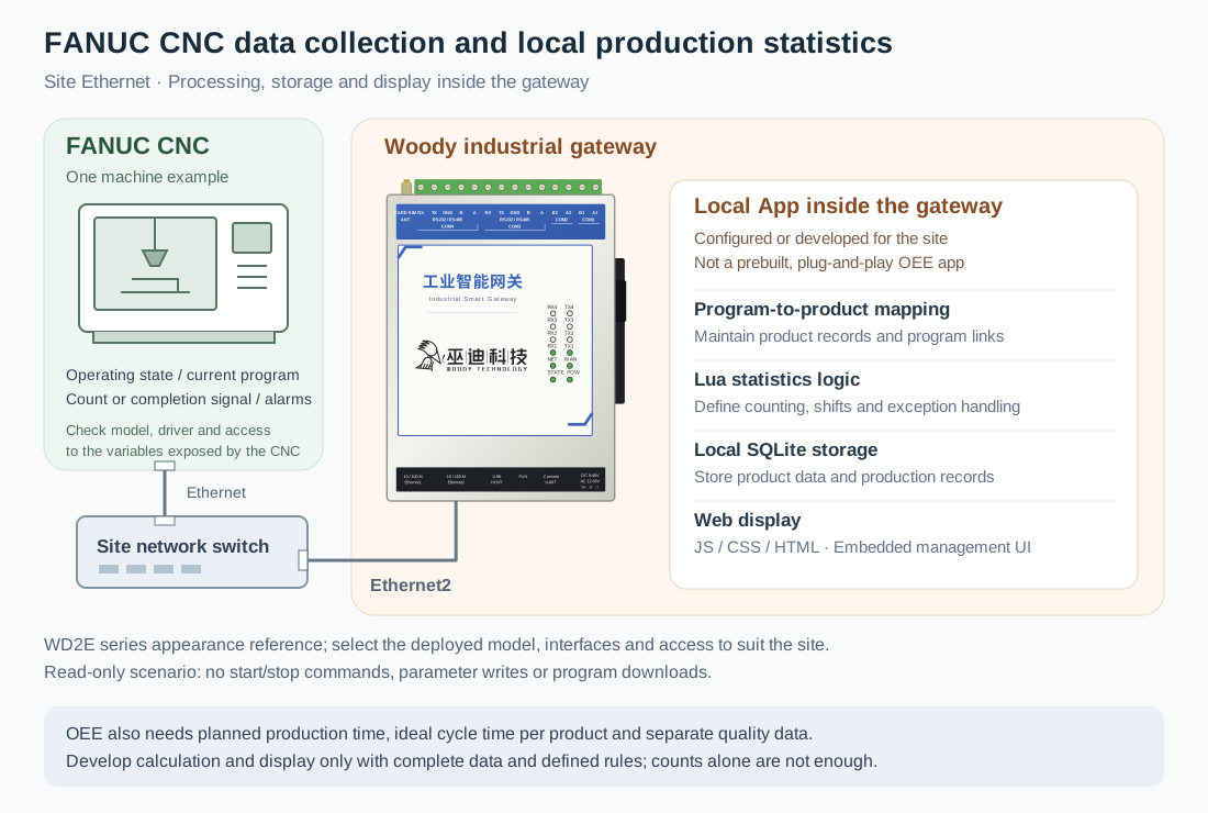
The diagram uses the shared WD2E-series appearance asset to illustrate the gateway. The actual model, interfaces, and connection requirements must be selected according to on-site conditions. This scenario only reads machine data; it does not involve remote start/stop, parameter writes, or machining program downloads.
Turn Machine Counts into Production Totals by Product
A counter value alone cannot answer "Which products did we make today?" A program name is not ready-made product information either. Someone needs to maintain the mapping between the two.
Process staff can maintain a product table in the local App's business forms, linking machining program names to product information. After the gateway collects the current program and a count or completion signal, the application identifies the product according to agreed rules, generates a production record containing machine, product, and time information, and saves it in the built-in SQLite database.
What matters most here is not the number of fields in the table, but whether the counting rules reflect the actual machining process:
- Distinguish cycle counts from production quantities. One machining cycle may produce multiple workpieces, or it may be a trial cut or a dry run. It must not be counted as good parts without verification.
- Define how records are assigned when programs change. Determine the assignment from the timing of program changes and counter changes. Flag records with unclear assignments for verification, rather than simply applying the latest program name.
- Handle counter resets and collection gaps. Operator resets, machine restarts, and communication interruptions can all affect records. Changes in a cumulative value must not automatically be treated as additional production without checking their meaning.
- Use consistent day and shift boundaries. Production and process staff should first agree on how overnight shifts are assigned and whether trial machining is included, then implement those decisions in the application's rules.
Once these conditions are confirmed, the local App can summarize records by date, machine, or product and display dashboards, reports, and trend charts within the gateway's Web management interface. Lua handles backend processing and business logic, while JS/CSS/HTML are used for frontend pages. The gateway provides the framework; the specific application must be configured or developed, and its counting results must be checked.
OEE Requires More than a Running Signal
With production records in place, the next step may be OEE, or Overall Equipment Effectiveness. It combines availability, performance, and quality to help the shop examine equipment utilization from different perspectives.
OEE = Availability × Performance × Quality
| Metric | Calculation basis | Required data |
|---|---|---|
| Availability | Run time ÷ Planned production time | Verified operating states, state records, and planned production time |
| Performance | Ideal cycle time per part × Total part count ÷ Run time | Each product's ideal cycle time per part, and total part count and run time determined using the agreed definitions |
| Quality | Good part count ÷ Total part count | Good part count and total part count covering the same reporting scope |
Machine states can provide a basis for calculating run time, but production and process staff need to define planned production time, downtime categories, and ideal cycle time per part. In this scenario, OEE should be displayed separately for each product and its corresponding reporting period. The same cycle time must not be applied to all products, and individual products' OEE values must not be added together or simply averaged to obtain a whole-shift result. If planned production time, run time, or total part count is zero, the corresponding ratio should be marked as not applicable. Incomplete data should be flagged for verification, rather than displayed as valid OEE.
Quality data also requires an independent source. A machining count does not prove that a workpiece meets quality requirements. Quality data can be entered through local App forms or obtained by integrating an inspection system, subject to its interface requirements. Without reliable quality data, display run time and production quantities first. Do not default the quality ratio to 100% or label estimated values as measured OEE.
Once the data is complete and the definitions are clear, OEE calculation and display logic can be developed in the local App. This is not a standard report automatically generated by the gateway, and an OEE figure alone cannot identify the root cause of downtime. Cause analysis also requires shop-floor feedback, alarm records, or a separately designed process for entering downtime reasons.
Review the Records at Handover, Then Verify on the Shop Floor
Once the application is implemented, supervisors can first review current states, product information, and shift records in the gateway's embedded dashboard, then investigate exceptions on the shop floor. Process staff maintain product mappings, while production staff view summaries based on the same definitions, rather than each working from manual readings taken at different times.
Pages should show the last update time and distinguish communication interruptions and stale data from actual downtime. These indicators and exception-handling rules need to be implemented in the application. A stopped status does not mean that the system already knows whether the cause is a material shortage, a tool change, or a fault; the relevant shop-floor information is still needed.
Local processing, storage, and display do not require a cloud platform or a separate application server. If centralized viewing across workshops or factories is needed later, data publishing through MQTT or HTTP/HTTPS and integration with a receiving platform can be configured separately. Platform-side reception, authentication, field mapping, and business interfaces still need to be implemented; they are not capabilities that become available automatically when the gateway is connected to a network.
Confirm Before Connecting
- Check the exact CNC model, driver compatibility, communication interfaces, access permissions, and exposed variables, and compare each item against the on-site display.
- Define program-to-product mappings, the meaning of counters or completion signals, record assignment during product changeovers, and record handling after counter resets or communication interruptions.
- Agree on shifts, planned production time, operating-state definitions, and each product's ideal cycle time per part, and prepare an independent source of quality data.
- Plan the App's forms, calculation logic, pages, and exception indicators, and assign development and maintenance responsibilities. Do not treat framework capabilities as a preinstalled business application.
- Plan historical data retention, backups, and access permissions according to storage resources and recording frequency. Do not assume unlimited retention or gap-free records.
A machining shop that wants a clearer view of production can start with state and production records from one machine. Once collection and counting definitions are verified, it can extend the application to product mappings, shift summaries, and OEE. The gateway makes machine data usable, the local App organizes it according to shop-floor rules, and production and process staff explain what those numbers actually represent.